
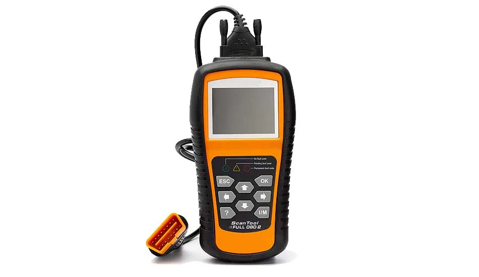
Computers are great most of the time, but when they don’t work, they’re a pain in the jacksie. Hooking up the scan tool only to be greeted with no communication is frustrating!!!
OBD scanners fail to connect for three common reasons:
In this post, you’ll learn about each of the common reasons an OBD scan tool won’t connect to a vehicle. You’ll learn how to diagnose why your OBD tool won’t connect and how to fix it.
When writing this post, I assumed your scan tool powers up when you plug it into your vehicle’s OBD port, but it just won’t connect.
If, however, your scan tool won’t even power up when you hook it up, then check out this post, “OBD scanner won’t turn on” It covers the simple fix in detail. A blown fuse is often the cause of a scan tool that simply won’t power up.
Or maybe your scanner just won’t clear the damn codes; if that’s you, then check out this post – OBD2 won’t clear codes
Otherwise, read on; you are reading the correct post.
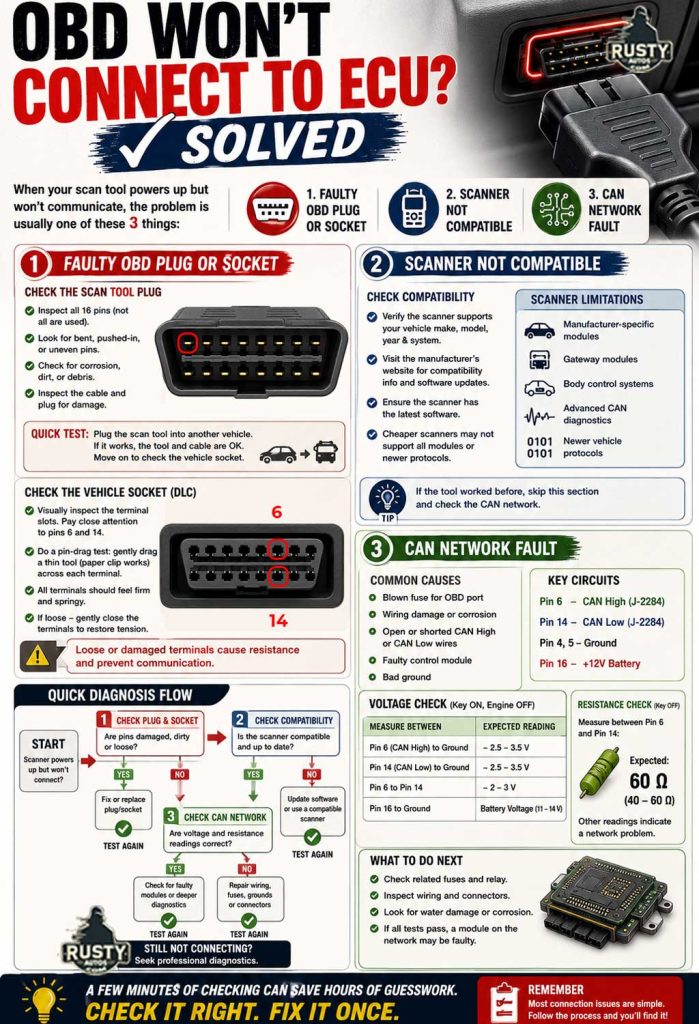
1 Faulty OBD Plug or Socket
This may seem simplistic, and you are correct, but it’s worth exploring for two reasons. Number one, it only takes a few moments, and number two, while not being the most common cause of a scan tool that won’t communicate, it is by far one of the easiest fixes.
So what’s the problem with the OBD plug/socket?
I’m a mechanic, and while we’re known for our MacGyver-type skills, we may not be generally prized for our finesse. That’s not to say we disrespect kit or customers’ vehicles, but working on a workshop floor is all about speed.
In a long-winded way, I’m saying your vehicle’s OBD connector, also known as the DLC (Datalink connector), may be damaged from possibly years of OBD scanning and, dare I say it, “Front probing.”
Reaching into a vehicle, blindly fitting, or pulling the scanner cable is a normal everyday occurrence. This type of repeated activity will eventually cause scan tool pin wear or damage and spreading of the vehicle’s female OBD socket terminals.
How to check the scan tool plug?


Examine your scan tool plug and check the pins. There are 16 pins. (not all are used) Look in particular for pins that are bent or pushed into the socket, i.e., a lot shorter than the others.
Check for corrosion or debris in the plug. Check the cable itself for damage, and check the plug at the scanner too. Finding a problem with the plug or cable is easy to fix. Most good scanners will have a detachable and, therefore, replaceable OBD cable. Just go ahead and buy a new cable. They’re not expensive.
Of course, a fast way to check your scan tools is simply to plug them into another vehicle if it works great! You can move on to a possible problem with your vehicle’s OBD terminals, and that’s what we’ll look at next.
How to check the OBD socket (DLC)?

Checking your vehicle’s socket is a little more work but not much. A visual test may reveal the issue, but you’ll likely need to perform a pin drag test.
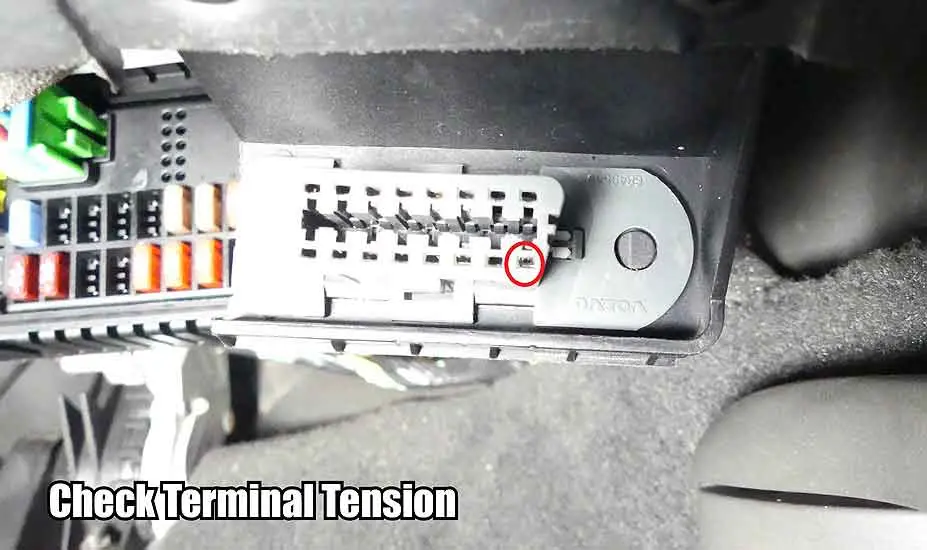
Your vehicle’s DLC terminals are known as female terminals. Wear and tear and front probing cause the terminal legs to lose tension. This causes resistance and often is the root cause of scan tool communication issues.
We’ll do what I said was rarely a good idea for this test. We’ll front probe the pins and compare tension.
A visual test comes first. Examine the DLC terminals closely. They should look similar. Note: not every DLC slot will contain a terminal. Pay particular attention to terminals 6 and 14. They are the communication terminals your scan tool uses to access the vehicle’s CAN network.
Next, we’ll pin-drag test the terminals. We’ll place a fine metal tool between the pins and feel the resistance when we remove it. This isn’t a measurable result. We’re using our ability to feel the difference in tension from one terminal to another.
In a workshop. We have very precise tools for this job, but you can still nail this test by improvising a fine paper clip or such. Do not place objects like a multimeter probe into the terminals. That will damage them.
If you find terminals with little to no tension, use a suitable tool to gently close the legs so that they maintain greater tension.
2 Scanner Not Compatible
The scanner you are using may simply not be compatible with your vehicle.

Of course, if you have used this same scanner previously and it worked, then this whole section doesn’t apply to you. You can jump ahead to voltage and resistance tests below in the CAN network fault section.
If, however, the scanner is new or new to you, go ahead and check your scanner’s capability. Check that it contains the latest software. Many tools offer free software upgrades. Try logging on to your scan tool makers’ website. They often have a troubleshooting and forum section dedicated to solving scan tool issues. Common scan tool problems will be front and center.
I get asked a lot if scan tools are universal, so I wrote a post about exactly that, and you can check it out here “Are OBD scanners universe.”
If you need an inexpensive scanner that does the job, check out the Topdon vs. Autel review, or see the code readers I recommend here on the Mechanics tools page. Or check out the Code Reader Amazon link below.
Amazon OBD Code ReaderCheap Scan Tools Have Limits
A basic code reader is great for simple engine faults, but communication issues are a different animal.
Many cheaper scanners struggle with:
- Manufacturer-specific modules
- Gateway modules
- Body control systems
- Advanced CAN diagnostics
- Newer vehicle protocols
That doesn’t necessarily mean the car is faulty.
Sometimes the scanner simply lacks the ability to communicate properly with the system.
In the trade, if communication gets weird, trying a second scan tool is often one of the quickest sanity checks.
3 CAN Network Fault
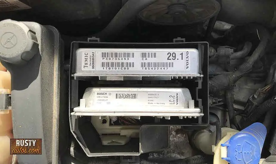
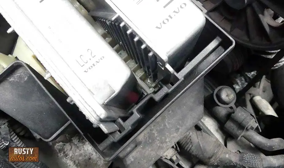
As you know, modern vehicle electrical systems increasingly employ control modules to manage system functions. Your vehicle will employ several. Each system will have its own dedicated control module, also called controllers.

Vehicle computers are known by several names and acronyms, and to make things even more exciting, manufacturers use their own names. But don’t let any of this confuse you; they all just control modules. Some of the common controller names include – Control modules, Controllers, Computers, CU, CM, Modules, and Microprocessors.
To identify individual controllers, manufacturers generally use acronyms like PCM (Powertrain Control Module), ECM (Engine Control Module), ECU (Engine Control Unit), TCM (Transmission Control Module), EBCM (Electronic Brake Control Module), or EBM (Electronic Brake Module), or BCM (Body Control Module), IPCM (Instrument Panel Control Module) you get the idea.
What Does a CAN Network Fault Actually Cause?
CAN faults can create some seriously weird symptoms.
Because modern modules all share information, one communication problem can affect multiple systems at once.
Common symptoms include:
- Multiple warning lights
- No crank no start
- Intermittent starting
- Transmission stuck in limp mode
- Power steering failure warnings
- ABS faults
- Gauges acting strange
- Windows or locks behaving oddly
- Scan tool won’t communicate
This is why CAN faults can feel overwhelming.
The problem may look huge, but very often the root cause is just one failed module, damaged wire, or low-voltage issue.
What does a controller do?

I’m not going deep into the weeds here, I realize you simply want your OBD to connect, but a little background info is useful for later when we run some tests.
As said, vehicles employ lots of controllers. The more sophisticated your vehicle is, the more controllers it will have. All modern vehicles, for example, will have an ABS brake system. This is a sophisticated system that only a computer can manage.
Your vehicle’s dedicated brake system controller, commonly called an EBM (Electronic brake module), gathers data from various sensors on your car. Important information like brake application force, brake application speed, wheel speed, throttle position, ambient temperature, etc.

The EBM processes the information and takes action according to its software parameters.
Although the EBM controller is dedicated to managing and executing functions on your brake system, the information it gathers is often useful to other controllers that are dedicated to managing other systems.
Controllers, therefore, share information. They don’t work in isolation. They are part of a network of information.
Controllers Share Data:
The PCM (Powertrain controller – manages engine and transmission) uses basic data like vehicle speed to perform timely fueling or gear change decisions. As the BCM already gathers speed data, it shares it with the PCM.
But the BCM may also share information about ABS activation. The PCM may use this information to cut power to the engine when the vehicle is skidding.
Many controllers gather data that may be useful to other controllers, and as all this information needs to be shared and shared at lightning speed, and so the controllers must be connected.
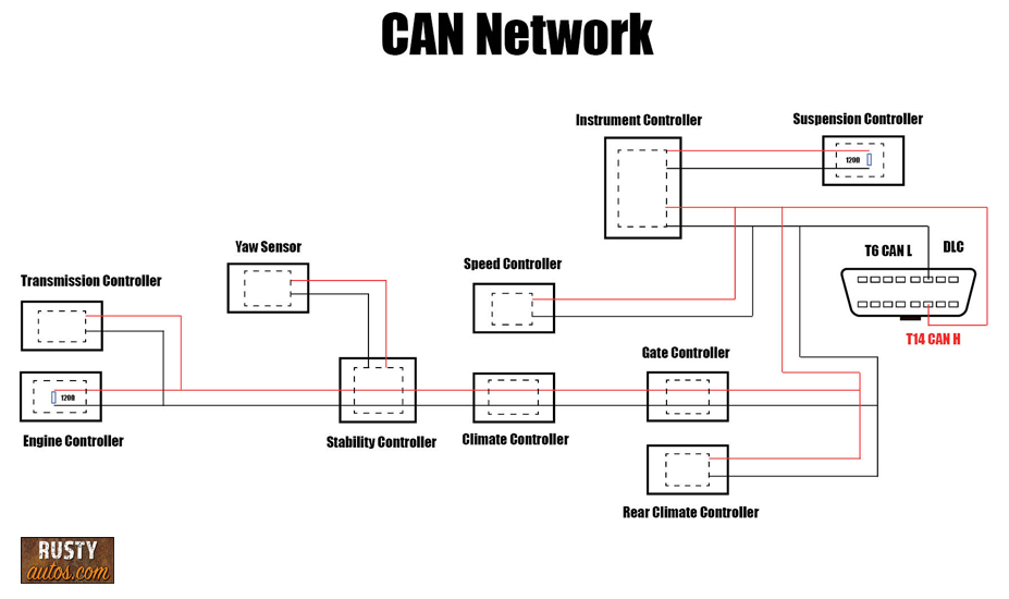
Controllers are connected via multiplexers which facilitate communication and the sharing of information. Modern vehicles typically use a few different types of communication systems depending on how important the message is. The most common system type is CAN (Controller Area Network).
Most systems use conventional wiring. Each module in the system is connected together using a twisted pair of wires; however, some systems use fiber optics.
How do they communicate?
CAN networks, as you know, connect all the controllers together using a twisted pair of wires known as the CAN lines. They are twisted because that helps reduce interference from other wiring circuits.

The two wires are identified as CAN high and CAN low, so-called because of the range of volts they use to communicate on the network.
The CAN high typically uses a voltage range of 2.5 to 3.5 volts, and the second wire, known as CAN low, typically uses a 1.5 to 2.5 voltage range.
Every controller on the system is recognized and monitored by all the other controllers on the system. It’s eyes on eyes. Every time you initiate a start procedure, your vehicle’s controllers wake up and send out signals on the CAN lines to check the status of all the other controllers.
They, in turn, signal back so that all the controllers talk to each other. It’s known as the handshake. Each controller has a set time to communicate. This is important. If all controllers talk at once, messages are lost.
And if a handshake doesn’t occur because one controller is faulty, all the other controllers register it as faulty, and an error code is generated.
The fault could also, of course, be a wiring issue between the suspected faulty controller and the network.
Because CAN network language uses voltage drops to communicate, they are super sensitive to changes in voltage; in other words, they are super sensitive to circuit resistance.
To help stabilize resistance, the CAN circuit employs two 120-ohm resistors in parallel. This using Ohm’s law, makes the measurable resistance of 60 ohms. That’s important to know for later when we’ll be testing circuit resistance.
The resistors are commonly controlled module integrated but may also be embedded in the circuit.
Low Battery Voltage Can Trigger False Communication Faults
Modern CAN systems absolutely hate unstable voltage.
A weak battery can create complete electrical chaos and trigger communication faults even when no module is actually bad.
I see this constantly on roadside calls.
Low voltage can cause:
- No communication with modules
- Random warning lights
- U-codes
- Modules going offline
- Intermittent no-start issues
- False sensor readings
Picture this:
One module wakes up slower than another during startup, communication gets interrupted, and suddenly half the car thinks the other half has died.
Before condemning controllers or wiring, verify battery voltage and charging system condition first.
Simple stuff first.
Common communication issues:
Communication circuit wiring chafing and breaks are common but not as common as controller failure. Controllers usually fail in two ways:
- They fail to work and stop communication completely – the other controllers register the controller as faulty.
- They contaminate the CAN network with constant erratic voltage. The other controllers and scan tools can’t understand this constant gibberish and simply don’t get a chance to shake hands with the other healthy controllers, as the CAN lines are always busy.
It’s not uncommon for one controller to become corrupt and pull down the whole network. This causes a no-start issue. Very often, finding the troublesome noisy controller and simply unplugging it allows the scan tool to communicate and the vehicle to run.
Aftermarket Electronics Can Interfere With CAN Networks
Not every CAN fault is caused by the vehicle itself.
Poorly installed aftermarket equipment can absolutely bring down communication systems.
Common offenders include:
- Cheap alarms
- Dash cams
- Radio installs
- GPS trackers
- Remote starters
- Towbar wiring kits
- LED lighting kits
I’ve seen badly installed radio systems completely kill communication with multiple modules.
Any accessory tied into CAN wiring incorrectly can create resistance issues or flood the network with electrical noise.
If communication problems started shortly after electrical work or accessory installation, that’s a huge clue.
Common reasons control modules fail:

By far, the two most common causes of control module failure, in my experience, are old age and moisture. Moisture caused by water leaks is a common cause of failure.
Many controllers that are fitted under the hood are pretty durable and can withstand moisture, but controllers fitted inside the cabin aren’t built to withstand moisture since they aren’t expected to get wet.
Common Places Water Damage Hides
Water intrusion is one of the biggest controller killers I see.
And the annoying part?
The leak often happens far away from the damaged module.
Common leak points include:
- Blocked sunroof drains
- Windshield leaks
- Door membrane failures
- Heater core leaks
- Cowl drain blockages
- Trunk seal leaks
- AC evaporator drain issues
Quick clues include:
- Damp carpets
- Condensation inside windows
- Musty smell
- Corroded connectors
- Green or white powder on terminals
Always lift carpets and inspect underneath carefully.
Some modules sit directly on the floor under the seats where even a small leak can destroy them.
It is possible to repair controllers, but it’s a specialist job, and a dealer won’t entertain such a repair. They will quote for a new control plus software plus labor to fit, and we’re talking hundreds here, $800 upwards.
Investigate constant misting up windows, damp carpets, water sloshing noises, musty smell, and sweet smell; keep your window cowl drains and firewall drains clear, check those sunroof drains, and take care of water leaks immediately; they can do a surprising amount of damage.
How to check the CAN System
Controllers are expensive and complex units. Calling one failed without doing the proper test can be costly. Many a good tech has been caught out by jumping the gun and calling a perfectly good controller faulty, only to find the problem is still present with a shiny new spendy one installed.
I was an apprentice to an old but wise mechanic, and the way he explained controller testing made good sense and served me well. I’m passing it on. Controllers are like black boxes. We don’t know what’s going on inside them, and we don’t really care.
What we do care about is verifying the following:
- Good voltage supply
- Good ground path
- Good inputs
Once we have checked the voltage, ground, and inputs, condemning a failing or faulty controller is easy.
The following tests aren’t complicated, and most of the checks are easy to do. This content is owned by moc.sotuaytsur. Some may be more challenging than others, not because of complexity but because some controllers may be difficult to access.
To test the circuits and controllers, we’ll need to check the voltage when the system is at rest (static voltage check) and the circuit when the circuit is live (volt drop test).
In addition, we’ll check the resistance of the CAN network. We’ll cover all these tests below, but before we do, we’ll need the proper tools to make these tests.
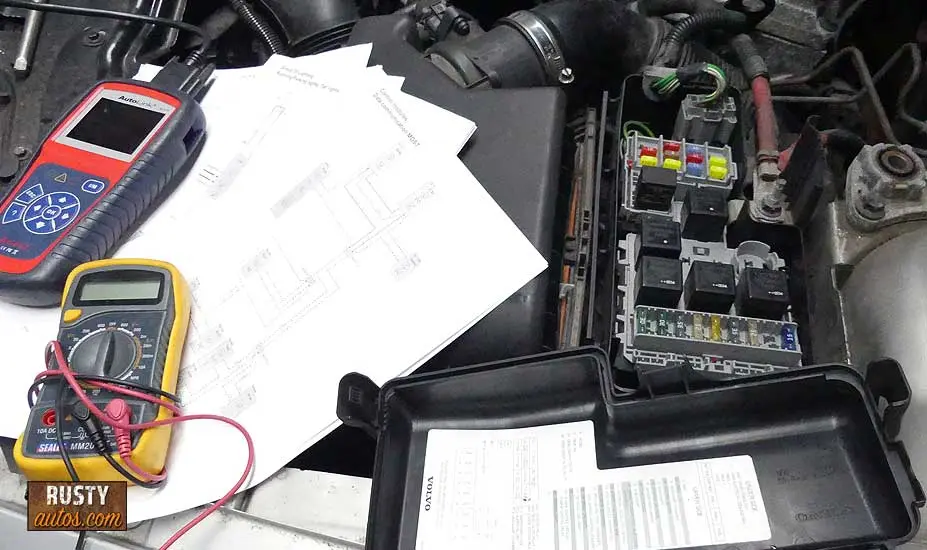
Tools we’ll need:

Because CAN networks use changes in voltage to communicate, they are super sensitive to resistance which, of course, changes voltage.
CAN networks communicate in a predictable square wave pattern? However, they do it at lightning speed. Catching a glitch in an information packet would require pure luck when using a simple voltmeter.
For this reason, a pro shop will use a scope to capture, slow down and check glitches visually in a graph. Having a scope does make capturing intermittent issues easier.
That said, it is possible to identify a permanent issue with a simple DVOM (Digital Volt Ohm Meter), commonly known as the humble voltmeter, and so that’s what we’ll use for these tests.
A wiring diagram will be needed for some of these tests as to how the CAN network is wired will predict some of the readings we should expect.
I wrote a post about reading wiring diagrams which you may find helpful – Beginners guide to reading car wiring diagrams
Tools we’ll need:
- Wiring diagram
- DVOM
- Probes
- Scope would be nice
Check out the Auto electrical repair tools page, where I list all the repair tools I use. Or check out the Amazon auto repair tools link below.
Amazon Auto Electrical Repair ToolsCheck CAN Voltage
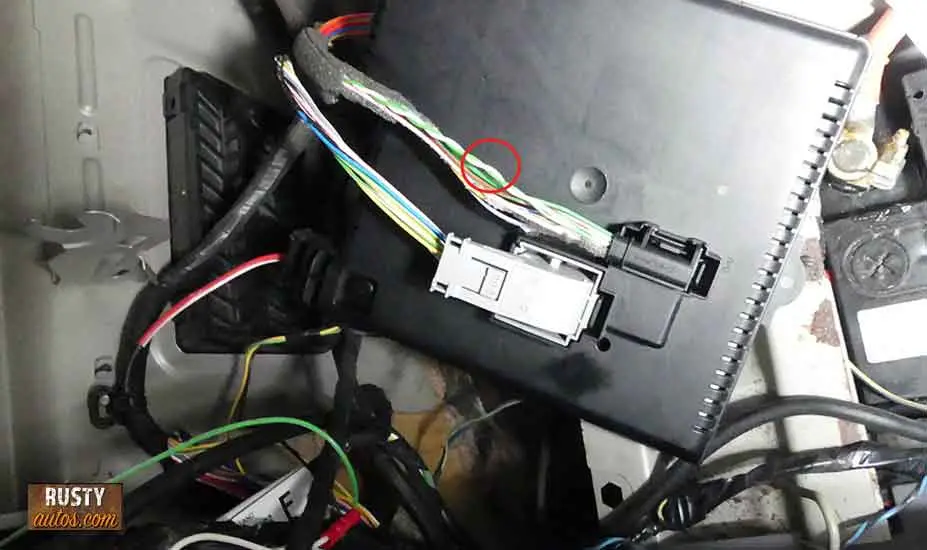
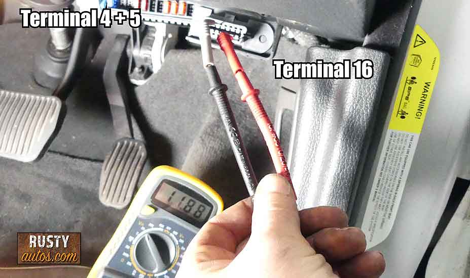
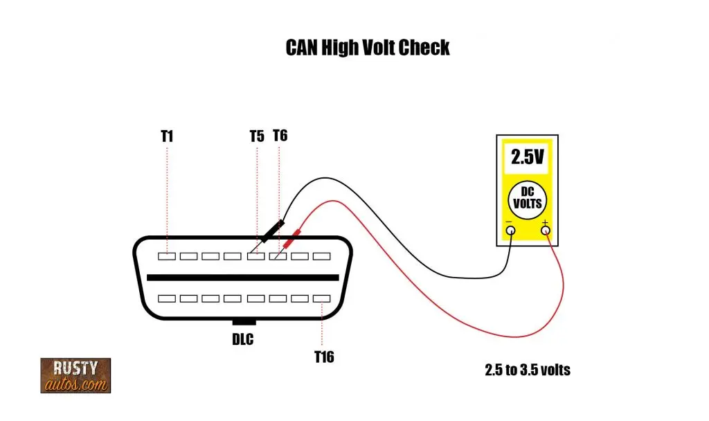
This is a simple voltage check using a voltmeter and fine probes. Remember, back probing terminals are advised unless you have fine non-invasive probes. Here’s a pinout of your vehicle’s DLC you can use to follow along.


As said at the beginning of this post, I’ve assumed you have power in the scan tool, but it isn’t communicating. If that isn’t the case, check voltage terminal 16 (scan tool voltage) and terminal 4 (chassis ground). Check terminal 16 and terminal 5 (signal ground) also. A blown fuse is often the cause of a scan tool that won’t power up.
A strong battery is critical. Low voltages may distort your results. A battery with min 12.5 volts should be maintained.
Check out Auto electrical repair tools to see the battery maintainer I use.
Check voltage at CAN High
Vehicle ignition should be turned on (Pos II). Place the positive voltmeter probe on terminal 6 and the negative on terminal 4. Use the min-max voltmeter function to capture the max voltages and min voltages. The readings between 2.5 and 3.5 volts indicate normal.

Check voltage at CAN Low
Vehicle ignition should be turned on (Pos II). Place the positive voltmeter probe on terminal 14 and the negative on terminal 4. Use the min-max voltmeter function to capture the max voltages and min voltages. The readings between 1.5 and 2.5 volts indicate normal.

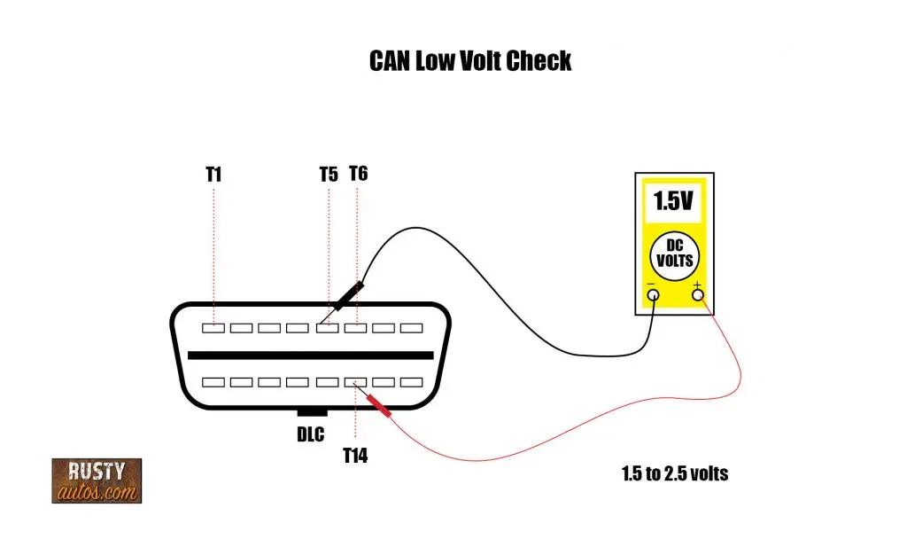
If either CAN high or low are outside, these readings jump ahead to circuit resistance checks.
Ground-side CAN voltage drop test
Vehicle ignition should be turned on (Pos II). With the voltmeter set to volts. Place the negative probe on terminal 4 and the positive probe on the chassis ground and note the reading. Repeat this for pin 5.

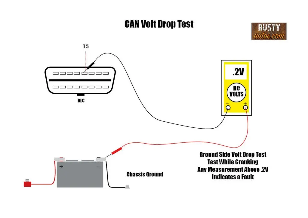
Both tests should read less than .2 volts. More than this means there’s excessive resistance in the circuit. The ground should be inspected first.
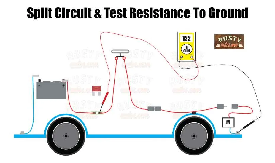
Check CAN Resistance

With the battery disconnected and the voltmeter set to Ohms. Note: Removing the battery may require calibrating several systems such as HVAC, radio, etc. In many cases, this may require a bidirectional scan tool.
I wrote a post about the systems it affects, which is included in this post – How hard is it to change car battery
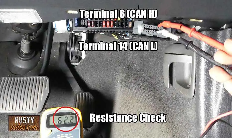
With the battery disconnected (ground terminal). Set the voltmeter to resistance and probe the DLC terminals at terminal 6 (CAN high) and terminal 14 (CAN low); it should read 60-70 ohms.
If you have a read outside this window, you’ll need to check a wiring diagram to verify where controllers are, how they are configured, and where the resistors are located.
A very large resistance or open suggests a broken or damaged wire, and you’ll need a wiring diagram to help isolate sections of the circuit to check continuity systematically.
If, on the other hand, resistance is lower or higher than expected but not open, then a faulty controller is a likely suspect. See checking the Controller diagram below.
Resistance test using wiring diagram
Depending on how your CAN network is wired. A process of elimination is often fruitful. Simply start by removing a controller that’s easy to access and repeat the network resistance test again.

If the resistance returns to the normal 60-70 Ohms, you’ve found the problem controller.
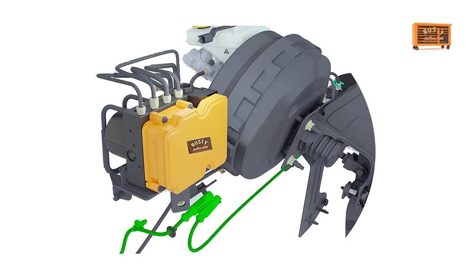
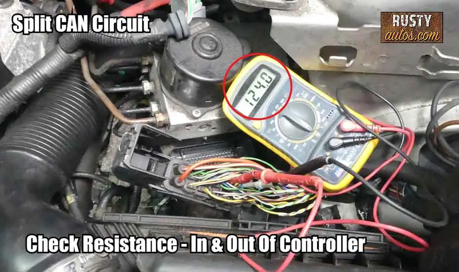
Most controllers are wired in series, with sub-controllers (Side streets off the main street); knowing which module is on the main street and which is a side street is crucial to efficient resistance testing.
Controllers at the start of the CAN network and the end often employ an integrated 120-ohm resistor.
Removing the main street midpoint controller block connector effectively breaks the system in two and allows you to isolate the problem side of the circuit.

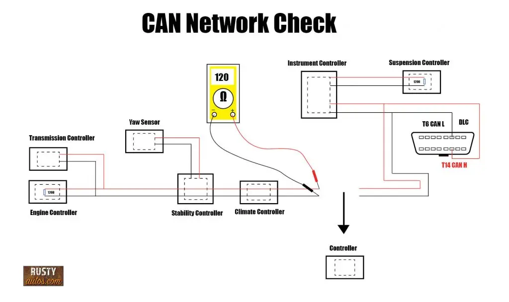
With the system in two halves, each end will contain a 120 Ohm (Ω) resistor, and since they are not connected and no longer in parallel, they will measure 120 Ohms or close to it.
Now, measuring resistance not at the DLC but instead at “CAN In” and “CAN Out” (at the disconnected controller’s block connector) will identify which side of the circuit is at issue. See the diagram above.
This process can be repeated repeatedly by reconnecting the controller and moving to another until the problem controller or wiring fault is isolated.
This, of course, is only possible if you have a good working wiring diagram. You must know wiring colors, routing, and pin-out numbers to test wiring circuits or controllers. Finding and fixing problems is straightforward once you have the power of knowledge.


When It’s Time to Call a Pro
Basic CAN testing is very doable for DIYers.
But there’s a point where advanced diagnostics starts requiring specialist tools and experience.
If you’re dealing with:
- Intermittent communication faults
- Multiple modules offline
- Fiber optic systems
- Gateway module issues
- Oscilloscope waveform analysis
- Programming or coding
…it may be more cost-effective to hand it over to a specialist auto electrician.
Modern communication systems are incredibly fast and sensitive.
One wrong diagnosis can lead to a very expensive guessing game.
Making repairs to the CAN network
Replacing a faulty controller will require a trip to the dealer, as the new controller will need to be coded to all the other controllers on the system. (Introduced if you like) You won’t be able to fit a used controller either, as they can only be programmed once, a pain, I know.
Who wants to pay through the nose for a new controller? In fact, doing so for many older cars just won’t make economic sense.
Alternatively, consider shipping just your controller to a specialist control module repair center; they will test and repair your controller without removing its software. Once repaired and returned in the mail, it’s a plug-and-play type deal. All by the way, for a fraction of the cost of a new main dealer-fitted unit.

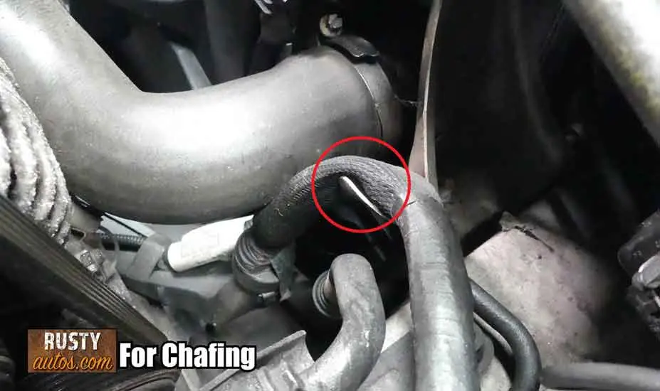
For wiring faults, you’ll often find chafed wiring under the hood where a loom turns direction sharply or around hot components like manifolds or EGR valves.
Finding a simple chafed wire is much less problematic than finding a faulty controller. Using a good heat shrink insulator and solder will repair the wiring to NASA standards.

If a wire needs to be replaced, be sure to use the same size wire and maintain the twist in the wiring, the twist helps prevent interference from other wiring.
FAQs
Why won’t my OBD scanner connect to my car?
The three most common causes are:
- Faulty OBD port or damaged terminals
- Scanner compatibility issues
- CAN network communication faults
In my experience, low battery voltage and poor connections are also huge causes of communication problems.
Can a bad battery stop a scan tool from communicating?
Absolutely.
Modern CAN systems are very sensitive to voltage.
A weak battery can cause modules to go offline or communicate erratically, which prevents the scan tool from establishing communication.
Before diving deep into CAN diagnostics, always verify battery condition first.
Why does my scan tool power up but not connect?
That usually means the scan tool is receiving power through the DLC, but communication on the CAN lines is failing.
Possible causes include:
- Faulty CAN wiring
- Failed module
- Damaged DLC terminals
- Wrong scanner protocol
- Corrupted network traffic
This is very different from a scanner that won’t power on at all.
Can one bad module stop the whole network?
Yes — and it happens more often than you’d think.
One failed controller can flood the CAN network with corrupted data or short the communication lines entirely.
When that happens, the scan tool may lose communication with every module on the vehicle.
I’ve seen one failed ABS module stop an entire car from starting.
What are the symptoms of a CAN network fault?
CAN faults can cause some seriously strange behavior, including:
- Multiple warning lights
- No crank no start
- Gauges not working
- Transmission stuck in limp mode
- Steering warnings
- ABS faults
- Intermittent electrical problems
- Scan tool communication loss
Because modules share information, one fault can affect multiple systems.
Can aftermarket accessories cause CAN faults?
Definitely.
Poorly installed aftermarket electronics are a common source of communication issues.
Common offenders include:
- Cheap alarms
- Dash cams
- Radio installs
- GPS trackers
- Remote starters
- LED kits
If problems started shortly after electrical work or accessory installation, that’s a major clue.
What should CAN voltage readings be?
Typical CAN voltage readings are:
CAN High:
Around 2.5V to 3.5V
CAN Low:
Around 1.5V to 2.5V
Exact readings vary slightly by manufacturer, but readings far outside these ranges suggest a communication problem.
Why is 60 ohms important on a CAN network?
Most CAN systems use two 120-ohm terminating resistors wired in parallel.
Using Ohm’s law, that creates a total network resistance of roughly 60 ohms.
A reading far outside that range often points to:
- Wiring damage
- Open circuit
- Short circuit
- Failed controller
- Missing terminating resistor
Can water damage stop OBD communication?
Absolutely.
Water intrusion is one of the biggest causes of module failure.
Common clues include:
- Damp carpets
- Condensation inside windows
- Corrosion on connectors
- Musty smells
- Random electrical faults
I always investigate water leaks seriously because modern modules hate moisture.
Can cheap scan tools struggle with communication faults?
Yes.
Basic scanners are often limited to generic engine systems only.
They may struggle with:
- Gateway modules
- Body control systems
- Manufacturer-specific protocols
- Advanced CAN diagnostics
Sometimes the scanner is the limitation — not the vehicle.
Can you drive with a CAN network fault?
Sometimes yes, sometimes no.
Minor faults may only trigger warning lights.
More serious CAN failures can cause:
- No-start conditions
- Limp mode
- Loss of ABS
- Loss of power steering
- Transmission issues
Because modern systems rely heavily on shared communication, CAN faults can escalate quickly.
Can a CAN fault drain the battery?
Yes.
A module stuck awake due to communication issues can prevent the vehicle from entering sleep mode.
That creates a parasitic battery drain and often leads to repeated dead battery problems.
Is replacing a control module plug-and-play?
Usually no.
Most modern modules require:
- Coding
- Programming
- Vehicle pairing
- Security setup
That’s why many replacement modules need dealer-level equipment or specialist programming tools.
Used modules can also create problems because many are locked to the original vehicle.
About the Author
John Cunningham is a Red Seal Qualified automotive motive technician with over twenty-five years of experience in the field. When he’s not writing about car repair, you’ll find him in his happy place – restoring classic cars.
Check out the Fault code page for Descriptions, symptoms, diagnosis tips, and the fix for all the common OBD fault codes.
Check out some common OBD common issues here in the Trouble Codes section.

Other posts you may find helpful

I wrote a ton of electrical fault-finding posts that hopefully you won’t need, but if you do, we have you covered.

Would You Know What To Do?
If your engine warning light came on tonight, would you know to keep driving, pull over, or call for recovery?
Most drivers wouldn’t.
That’s exactly why I wrote this guide.

- About the Author
- Latest Posts


John Cunningham is an Automotive Technician and writer on Rustyautos.com. He’s been a mechanic for over twenty-five years and has worked for GM, Volvo, Volkswagen, Land Rover, and Jaguar dealerships.
John uses his know-how and experience to write articles that help fellow gearheads with all aspects of vehicle ownership, including maintenance, repair, and troubleshooting.